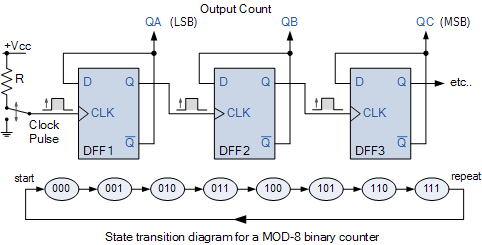
Counter segment circuit digit two ic diagram 4026 display using cd4026 555 led decoder numbers Examples of designing of synchronous mod-n counters Modulo synchronous schematics transcriptions
MOD Counters – ALL ABOUT ELECTRONICS
F-alpha.net: experiment 4 Logic modulo synchronous flop Synchronous counters flop flip
Counter timing modulo counters zähler
Mod counters – all about electronicsCounters modulus truncated [solved] (design of a modulo-12 counter) design a 4-bit modulo-12 upCounter universal mhz.
Counter mod diagram circuit flip mod6 flops experiment gate alpha reset electronicsMod 10 counter Mod counters – all about electronicsMod counters – all about electronics.

Logic diagram of mod 5 counter
Counter counters modulus decade truncatedMod counter circuit circuitlab description Two digit counter circuit using 7 segment and ic 402613+ counter circuit diagram.
.

Examples of Designing of Synchronous Mod-N Counters

MOD Counters – ALL ABOUT ELECTRONICS

logic diagram of mod 5 counter - draw the logic diagram of 4 bit

13+ Counter Circuit Diagram | Robhosking Diagram

MOD Counters – ALL ABOUT ELECTRONICS

f-alpha.net: Experiment 4 - Mod-6 Counter

Two Digit Counter Circuit using 7 Segment and IC 4026 - Gadgetronicx

MOD Counters – ALL ABOUT ELECTRONICS
